Crease moldings

scratch-stock molding in oak

Today I was making some moldings on the faces of framing parts for the cupboard I’m making. I can’t remembe when I last showed these, so thought I’d add this post. I call them “crease” moldings – from 17th century references to molding planes. There’s mainly three kinds of moldings I see – applied moldings (I’ll skip them for now) and two sorts of integral moldings. Those on the edge of a board and those that run down the center of the stock. While lots of moldings were probably made with creasing planes, some were not. I make the ones down the middle with a plow plane and a scratch stock/scraper.

Here’s just a couple of references to start off – these are probate inventories from New England. 

1661 Jonathan Proudfoot, Cambridge

2 frameing Sawes 6s,  a Handsaw 3s,  3 axes 10s,  a 2 foote rule 12d, 5 chessels & a gouge 2s6d,  2 Squares 3s6d,  Twibell 3s,  an ads 2s,  an Holdfast 12d,  2 Hamers 2s,  5 planes 9s,  a plow to draw boords 2s,  a stocke shave 1s,  9 creasing planes 8s, a peece Sole leather 12d,  a grindstone & winch 8s,  10 peeces of Square Timber 1£,  pine boords 12s

Another reference, this time from Essex County

1675,  Georg Coall (Cole)

 will:  “…I give to my master John Davis all my timber…”

3 saues 8s,  2 goynters & foreplaine 6s, 3 smothing plains & a draing knife 3s6d, 2 plans & 2 revolvong plains 10s,  4 round plains 5s, 3 rabet plains 4s,  3 holou plains 3s6d, 9 Cresing plains 10s6d,  6 torning tools 9s,  3 plaine irons & 3 bits 1s6d,  1 brase stok, 2 squares & gorges 1s6d,  1 brod ax & 1 fro 2s, holdfast 1s6d,  hamer 1s6d,  6 gouges 2s,  9 Chisels 5s,  2 ogers & 1 draing knife 3s,  1 bench hooks, 2 yoyet irons 1s,  a gluepot 1s6d,  for what work he has done in his shop £1-10

Interesting that in George Cole’s case the planes are distinct from the hollow & round planes listed before them. Revolving planes – goodness knows. Might be a mis-transcription too, I’ve never seen the original of this document, only a transcription. 

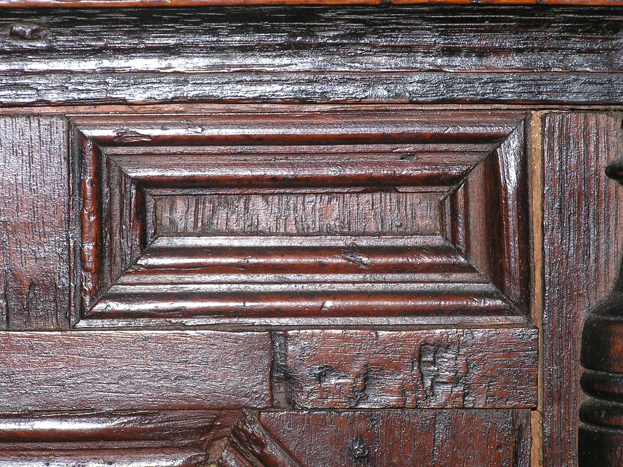
So some moldings are made with planes for certain. But for many of mine, I use a scratch-stock (a profiled scraper in a wooden stock). Why? Well, in addition to the inventory references, there’s the evidence on surviving furniture. Look at this wiggly molding on a small joined chest from Dedham Massachusetts:

detail, chest from Dedham Massachusetts

And another from the same shop – here the molding on the top and middle rails fades out before reaching the end of the stock. 

detail chest with drawer, Dedham Massachusetts

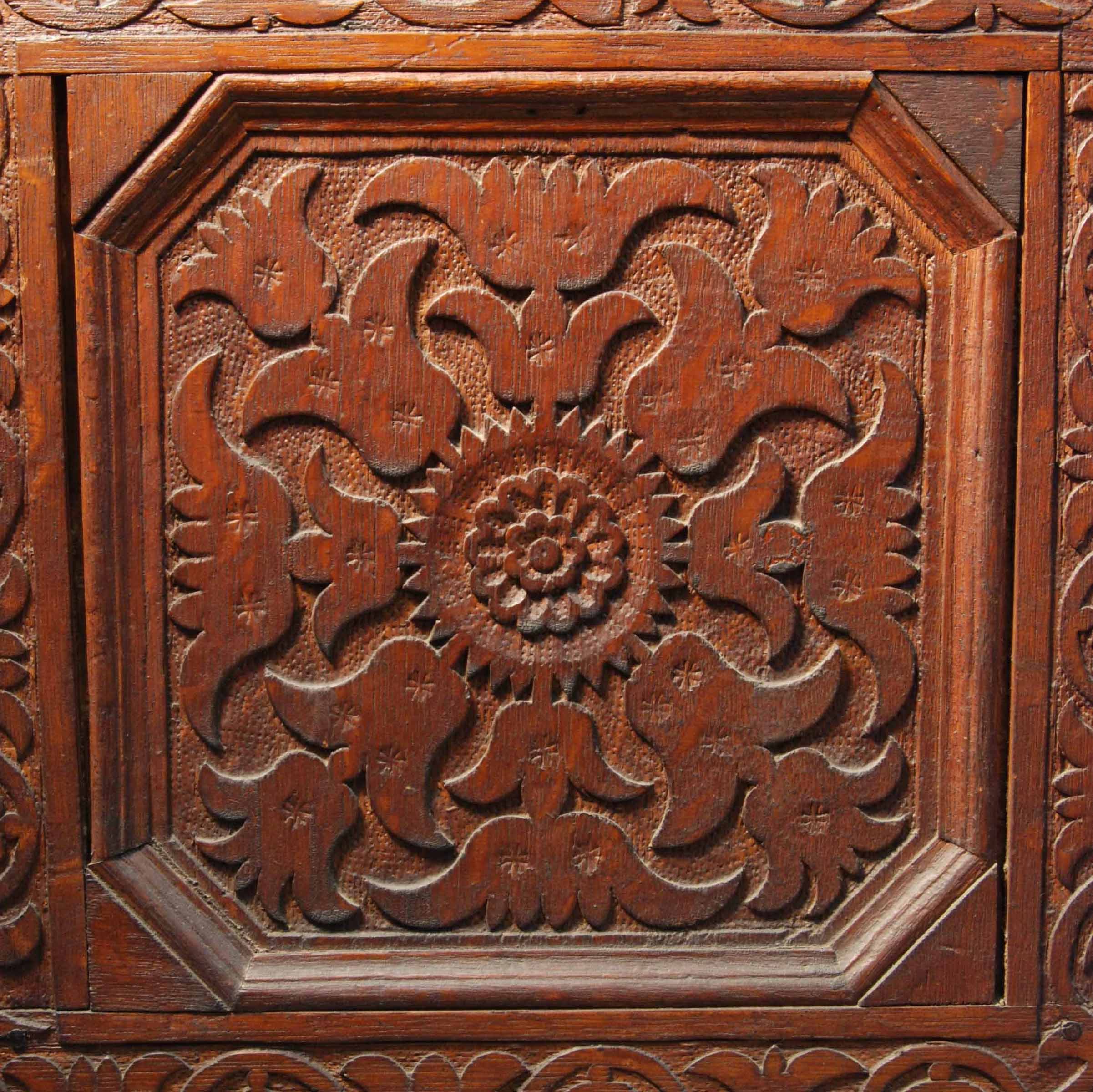
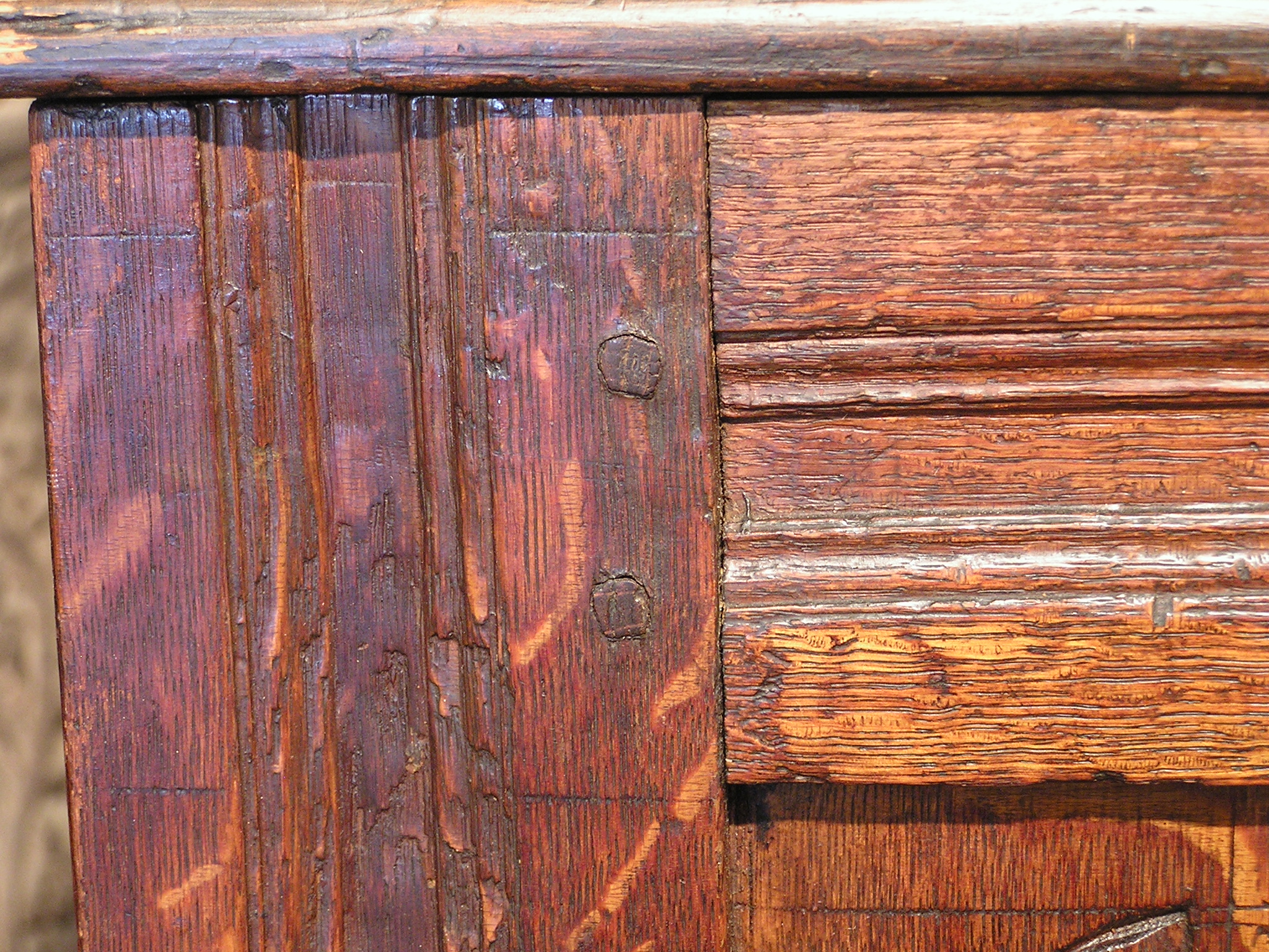
I think both of these results are hard to get with a plane. And another argument for scraping some moldings is this chest from New Haven Colony – its molding has its full profile then in a very short distance it fades to almost nothing. Again, I can’t see how you can cut that with a typical molding plane with a body of any reasonable length. 

detail joined chest, New Haven Colony

It’s especially significant over the middle panel – in that case the whole run of molding is only about 10″ long.

detail over middle panel, New Haven chest

The ones I was cutting today come in two steps. First I plow a groove 1/2″ wide down the length of the stock.

plowing a groove first

Then I use a scraper/scratch stock I made to scrape the profiles on each side of the plowed groove.

scratch stock

We have no idea what the scraper/scratch stock of the 17th century was called or what it looked like. So mine’s just what works easily. I made it like a marking gauge, adjusted by a wedge fence. The scraper slips into a saw kerf in the beam. then pinched in place with a screw.

scratch stock

Joseph Moxon describes a tool on a trammel which he calls a “sweep” for making moldings on arches. It’s hard to tell if his scraped or cut the moldings like a plane does…but it’s the closest I’ve come in 17th century writings to describing a scratch stock. And it ain’t close really.

Moxon’s sweep

Moxon on the turner’s sweep,

Of laying Moldings either upon Mettal, or Wood, without fitting the Work in a Lathe

I Had, soon after the Fire of London, occasion to lay Moldings upon the Verges of several round and weighty pieces of Brass: and being at that time, by reason of the said Fire, unaccomodated of a Lathe of my own, I intended to put them out to be Turned: But then Turners were all full of Employment, which made them so unreasonable in their Prizes, that I was forc’d to contrive this following way to lay Moldings on their Verges.

I provided a strong Iron Bar for the Beam of a Sweep: (For the whole Tool marked (D) in Plate 16, is by Mathematical Instrument-makers called a Sweep) To this Tool is filed a Tooth of Steel with such Roundings and Hollows in the bottom of it, as I have intended to have Hollows and Roundings upon my work: For an Hollow on the Tooth, makes a Round upon the Work; and a Round upon the Tooth makes a Hollow upon the Work; even as they do in Molding-plains Joyners use. Then I placed the Center- point of the sweep in a Center-hole made in a square Stud of Mettal, and fixed in the Center of the Plain of the Work, and removed the Socket that rides on the Beam of the Sweep, till the tooth stood just upon its intended place on the Verge of the Work, and there screw’d the Socket fast to the Beam.

To work it out, I employ’d a Labourer, directing him in his Left Hand to hold the Head of the Center-pin, and with his Right Hand to draw about the Beam and Tooth, which (according to the strength) he us’d, cut and tore away great Flakes of the Metall, till it receiv’d the whole and perfect Form the Tooth would make; which was as compleat a Molding as any Skillfull Turner could have laid upon it.

Having such good Success upon Brass, I improv’d the invention so, as to make it serve for Wood also. And make a Plain-Stock with my intended Molding on the Sole of it, and fitted an Iron to that Stock with the same Molding the Sole had.

Through the sides of this Stock I fitted an Iron Beam, to do the Office of the Beam I used for the Sweep, viz to keep the Plain always at what position I lifted from the Center (for thus the Iron in the Plain wrought about the Center, even as the Tooth in the Sweep (before rehearsed) and to that purpose I made a round Hole of about half an Inch Diameter near the end of the Iron: then in the Center of the Work I fixed a round Iron Pin, exactly to fit the said round Hole, putting the round Hole over the pin, and fitting the Iron onto this Stock commodious to work with. I used this Plain with both hands, even as Joyners do other Plains: For the Iron Pin in the Hole of the Beam kept it to its due distance from the Center; so that neither hand was ingaged to guide it.

But note, The Stock of this Plain was not straight (as the Stocks of other Plains are) but by Hand cut Circular pretty near the size of the Diameter of the intended Molding; And yet was made to slide upon the Beam, farther from or nearer to the Center, as different Diameters Verges might require.

moldings

I have been cutting some moldings lately for a chest with drawers I’m building. The moldings surround the panels, and the drawer fronts. While I was cutting these, I was thinking about this blog. I started it in 2008, and never thought it would keep going this long. Because I didn’t know what I was doing, I never really organized it well. So there’s lots of photos spread out all over the blog that are useful…but sometimes hard to find. Today, I thought I could just post some photos of period moldings found on New England joined works. So here’s pictures.

a chest from Salem, Massachusetts: Tearout, anyone?

moldings detail

a chest with drawers, Plymouth Colony. This large molding (2″ tall) is integral to the rail, not applied.

molding details, Plymouth Colony chest

Inside one of the Plymouth Colony chests, moldings on the rails and muntins:

interior, Ply Col chest w drawers

Here’s a panel detail from Plymouth Colony. This is a common profile for the period, technically an ogee with a fillet, I think:

molding-details

This one’s from Chipstone’s website – a Boston chest panel:

cf-chest-middle-panel-just-moldings

This is a muntin from a chest made in Braintree, Massachusetts. I used to make this molding with a scratch stock. I think that cutter is gone now…

molding

This Connecticut (Wethersfield? Windsor? I can never get it straight) chest with drawers was the model we copied last time at Connecticut Valley School of Woodworking. These moldings are oak:

center panel_edited-1

A lousy photo, but if you squint at the ruler’s shadow, you can see the profile of this molding. Dedham Massachusetts chest.

OLYMPUS DIGITAL CAMERA

Also Dedham, different chest:

OLYMPUS DIGITAL CAMERA

Back to Connecticut, more Wethersfield, Windsor, etc.

vine-carving-3

a drawer from a Woburn, Massachusetts cupboard:

molding-detail

An ogee on the bottom edge of a table’s apron. Maybe this square table is Boston?

ogee-and-bracket


scratch stock evidence

OK – so about scratch stocks in the 17th century. How did they make moldings on joined works? We know they had molding planes, there are a few from the 16th-century shipwreck the Mary Rose. And they appear in many probate inventories too; the following are some examples of molding planes found in New England inventories:

2 revolving plains

4 round plains

3 rabet plains

3 holou plains

9 Cresing plains

inboring plaines

Joseph Moxon & Randle Holme both call them by classical names too; ogees, bolection, and so on.

But look at the molding above the center panel in this detail shot of a joined chest from New Haven, CT.  (I clipped this photo out of Victor Chinnery’s book Oak Furniture: the British Tradition. If you don’t have that book & you like this blog, get it)

New Haven chest detail

The molding fades in & out at the juncture between the horizontal rails and the vertical muntins flanking the panel. This amounts to a run of about 9” or so. Not more than 10”.

In that length, the molding reaches its full profile in the middle, but is shallower and not fully defined at each end. I think you can’t do that with a molding plane – the length of the plane’s sole would prevent you from reaching that full-depth in such a short run, while still fading out before the muntins. Says me.  One of mine:

PF joined chest

To do this in my shop, I use a scratch stock. But I don’t know the history of this tool. I do know I have never seen it by that name in any 17th-century records. There is one reference I know of that describes using a scraping action to define moldings – in Moxon, but on Turning, not Joinery.

“Of laying Moldings either upon Mettal, or Wood, without fitting the Work in a Lathe.

I Had, soon after the Fire of London, occasion to lay Moldings upon the Verges of several round and weighty flat pieces of BrassL And being at that time, by reason of the said Fire, unaccomodated of a Lathe of my own, I intended to put them out to be Turned: But then Turners were all full of Employment, which made them so unreasonable in their Prizes, that I was forc’d to contrive this following way to lay Moldings on their Verges.

I provided a strong Iron Bar for the Beam of a Sweep: (For the whole Tool marked in Plate 16, is by Mathematical Instrument-Makers called a Sweep) To this Tool is filed a Tooth of Steel with such Roundings  and Hollows in the bottom of it, as I intended to have Hollows and Roundings upon my Work: For an Hollow on the Tooth, makes a Round upon the Work; and a Round upon the Tooth, makes an Hollow on the Work, even as they do in the Molding-Plains Joyners use…”

He goes on in great detail, talks about using this sweep to shape moldings in brass, then having success at that, took on wood too. (it’s pp. 217-219 in the section on turning).  Here is the tool Moxon’s engraving of the tool he claims to have invented; probably adapted would be a better term.

Moxon's sweep

Here’s one Bob Trent & I had made by Tom Latane back in 2001 when we did an exhibition at Chipstone’s installation in the Milwaukee Art Museum. Latane does some of the nicest blacksmith work I know.

sweep by Tom Latane

I know the sweep is a rather specific tool, but for me the idea is that with it, the workman scrapes moldings, rather than shave them as you would with a plane. that’s the driving point in the search for scratch stocks…

Here is an 18th-century engraving, from Roubo, about a tool like our modern scratch stock. I got it from Greber’s History of the Woodworking Plane. I didn’t look up the translation.

Roubo, from Greber's History of the Woodworking Plane

Here is a funny old tool I bought one day, because it almost is a scratch stock. It’s probably a coach-maker’s molding cutter. It’s sort of like a spokeshave, its blade is not perpendicular like a scratch stock, but more pitched like a true plane. But clearly a home-made job. Screwed together. The sole of this tool is quite short, maybe an inch long. Curved too.

a detail

One more

In this last view, you can see that it’s one piece of wood that’s been sawn in half, then screwed back together. I would look in Salaman’s Dictionary of Woodworking Tools, but it’s in the shop – and I’ll probably forget once I get there.

I’m sure there’s more, but that’s enough for today. I have a book to finish up.

scratch stock moldings

crease molding Dedham chest

The photo above is a detail of a joined chest’s top rail-to-stile joint. There’s a few things to see, but right now I want to draw your attention to the molding run on both framing members. This is what we think a “crease” molding is; one run down the midst of the stock rather than at the edge.

To cut this molding, you can use a dedicated molding plane, or a couple of them. Wait for Matt Bickford’s book to get the hang of that.  http://lostartpress.wordpress.com/2011/10/12/kill-your-router-raney-thinks-so/

Until then,  you can cut them with a plow plane and a scratch stock. That’s how I do most of them.

plowing a groove

Here, rather fundamental stuff – a wooden plow plane set to cut a narrow groove down the middle of a stile for the chest. To hold the stock on the bench, I just pin one stile down with a holdfast, then shove the workpiece against that, and up to the teeth of the bench hook (planing stop).

I measured the stile’s width, marked the center, then set the plow plane so its blade hit the point I had scribed. I eyeball the depth of the groove. I tend to start at the forward end and get the groove running, then lengthen each successive stroke to gradually make the grooves full-length.

Now I use a scratch stock made from an old scraper blade, or saw steel. I filed the shape into the end, then mounted the cutter in a wooden stock that works like a marking gauge.  Set it to cut this ogee shape down one side of the groove:

scratching first half of molding

Then, re-set the scratch stock, and run the other molded edge.

the other half

To check the shape, I just lay a piece of scrap wood on edge across the rail, and look at the shadow made from it. This helps you see the definition of the profile.

finished molding

In the midst of making these moldings, I remembered a new technique I sorta learned from watching Matt Bickford – once I cut the plowed groove  down the length of the stock, I take a round plane & start a bit of a hollow – with the plane riding in the groove. This just gets some of the waste out of the way before scraping the actual profile.

round plane removes waste

Here’s another look at a period example:

molding detail, joined chest Dedham MA 1650-1680

Simple stuff. Notice on this period example how the profile runs out towards the shoulder of the rail; or the upper end of the stile. It’s best to scrape this molding on stock longer than you need, then you more easily hit the entire profile the full length of your finished stock…but if it doesn’t make it …the chest will still hold linen.

molding runout

Here is the carved panel with that molded framing around it, had the camera a bit tilted. This and the previous are from old slides;  so not the best views. Often either the central plowed section or the entire molding is painted black.

carved panel, frame w moldings